| home |
| vanagon |
| ej22 engine |
| SSM params |
| typical values |
| analysis |
| trouble codes |
Further Analysis & Notes on SSM Parameters
Air/Fuel TrimThe air/fuel trim or air/fuel correction is the increment applied to the fuel injection to bring the air/fuel mixture (as sensed by the oxygen sensor) closer to the stochiometric ratio.
example 1Here is a graph of the correlation between the OxS and the air/fuel correction during various engine operating conditions: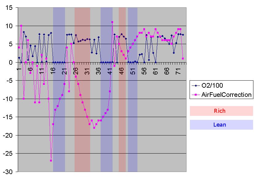
example 2Here is an example during acceleration, deceleration, and steady state operation (with an additional effect of the knock sensor):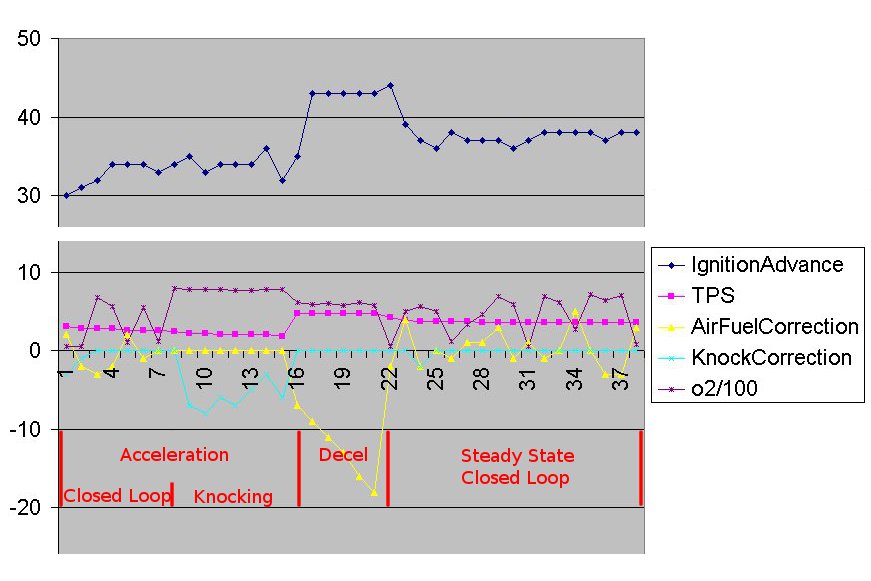
Mass Air Flow Sensor (MAF)The MAF measures the amount of air being used for the air/fuel mixture.example 1This plot shows the MAF reading and throttle position sensor (TPS) for acceleration from 0-60 through 3 gears (the TPS returning to closed at the shift time), then deceleration back to 0.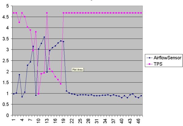 The air flow reading is roughly inverse of the TPS, as expected - the wider open the throttle, the more air entering the engine. Load CalculationThe engine load is essentially the mass of air consumed per revolution of the engine. The greater the mass per revolution, the greater demand on the engine for output power.The load is calculated using the MAF (mass/time) sensor and the RPM (rev/time) from the cam/crank sensors: mass/time / rev/time = mass/rev For the EJ22's air flow meter, it looks like the air mass is proportional to the cube of the AFM voltage. Subaru's calculation is something near the cube of the AFM voltage divided by the fraction of a max RPM: (AFM voltage)^3 / (RPM / 10000) example 1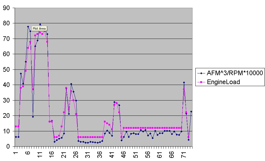 Injector Pulse Width CalculationThe Injector Pulse Width, or IPW, is the time in ms that the ECU keeps each injector open during the intake stroke. The constant fuel pressure from the regulator means a somewhat linear relationship between the time open and the fuel volume delivered (not accounting for variations in temperature, etc.).The IPW is primarily dependent upon the engine load, which from above can be seen to be the mass of air per rev of the engine; a larger mass of air requires a larger amount of fuel to maintain a stochiometric ratio. (Other corrections are applied at different running conditions, such as starting - where the IPW is increased to provide a rich mixture for easy starting.) The EJ22's IPW maps follow something like: Engine Load^0.6 - 3 (the EG33 factor is closer to 0.62) example 1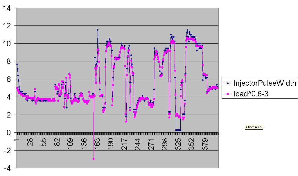 Engine Timing CalculationEngine timing is primarily dependent upon the RPM of the engine and the calculated load. At higher RPMs, the timing is advanced; at larger loads, the timing is retarded.This EJ22 ROM's (7232xx) timing maps look something like: (RPM/100)^1.1 - (Load over 60) + 10 example 1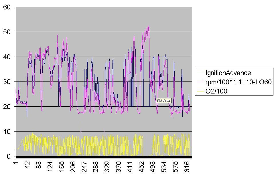 Notes:
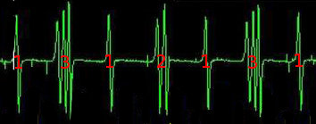
Cam & Crank Angle SensorsThis oscilloscope plot shows the relationships between the cam and crank angle sensors, the engine timing, and the injector signals (thanks subaru vanagon yahoo group user "ric8721" for the capture). A trace such as this can be used to diagnose a slipped timing belt.
Channels:

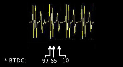
(And, here is a plot of the same engine, mistimed (the timing belt had slipped): 
Note that the injector and spark signal are not near the 10*BTDC timing mark used for the starting condition.) Binary ParametersThe 16 useful binary parameters in the Subaru ECU are located at two separate memory addresses (bytes), each with 8 bits of information. Each shows the state of 8 switches (mechanical and/or electronic) which are used as inputs for the ECU. Finding the individual binary values requires decoding the byte by bit number. Here are the bit orders within the bytes:
For example, a retrieved value of '152' for the second switch byte represents a binary value of 10011000 - showing the idle switch, radiator fan, and fuel pump active, and all other switches off. (Examining the individual bits of the binary parameter bytes can be done in Excel. For example, if column Z contains the second byte of binary parameters, using DEC2BIN(Z1,8) shows the binary equivalent of the byte. Each individual binary parameter can be isolated as such: MID(DEC2BIN(Z1,8),1,1): idle switch bit MID(DEC2BIN(Z1,8),4,1): radiator fan bit etc.). (*) The SSM parameter list includes another binary parameter called "O2 Monitor", described as "A/F ratio is rich". This parameter appears in a separate SSM "mode" (which corresponds to a byte of data in the ECU for the other binary parameters). It is unclear where in the ECU memory this byte/parameter appears, and I have not seen an aftermarket monitoring program which correctly locates it. ROM IDsthe 1990-5 EJ22 ECU is a dedicated on-board computer which takes as input readings from sensors on the vehicle and engine, and calculates engine parameters such as fuel injector duration. the dynamic values of the sensors and calculations can be found in the ECU at one of 32000 addresses in memory.subaru select monitor diagnostic tools (like the B10 and even subaru's own 'select monitor' used by suby mechanics) work by reading dynamic engine parameter values out of the ECU's memory at those addresses. however, here's the rub - over the years the EJ22s were shipped with many different versions of the ECUs. as subaru worked on the software the memory addresses changed, so any parameter (like the RPM or TPS) could appear in one of many different memory addresses depending upon when the car/ECU was manufactured and in what market (european, US, JDM). so, how does diagnostic software know where in memory to find its values? each ECU has a ROM chip which can be queried for its version number. knowing that version number allows the software to look up the table of addresses for each sensor and parameter for that particular ECU. subaru is the only entity which knows for sure the full contents of that lookup table of memory addresses for any given ROM ID. since they never gave out that information, any EJ22 diagnostic software author had to find the addresses in one of 2 ways: they could hook up a mechanic friend's real factory subaru select monitor (which has the correct ROM addresses for all the ECUs ever made) and intercept the communication to the ECU; or barring that, it was a trial and error process of looking through over 32000 memory addresses to find suspicious looking numbers changing in the right way as they drove or revved the engine! whether or not the addresses for any given ROM were found depends upon whether someone had an ECU with that particular ROM series and the patience to find them. over the years tables of addresses for some of the ROM series were found...but many were not. of those found, i've seen some that have bad addresses for the parameters, and some that have correct addresses but incorrect conversions. for example, for your particular ROM, the tool might read everything correctly except the VSS. (in addition, each of the parameters found in memory uses one of 12 pre-set conversion factors to convert it into a real-world value for use by a mechanic. in more than a few cases, the tables used by the B10 tool and other software also have some of those conversions factors wrong.) these ROM tables have been passed around the subaru legacy and internet communities for years, with errors and omissions intact. any new software uses the same tables. evaluate carefully the values you get from your aftermaket tools.... |