Shimano Deore LX RapidFire Plus 3x8 Shifter Rebuild

How hard is it to rebuild? If you're good at handling small pieces, and are methodical about taking pictures and keeping notes, it's not too hard at all. Is it worth it? Well...hmmm...especially if (like me) you like seeing how the Japanese engineers designed these precision mechanical components.
When rebuilt, these things work like magic. Unfortunately, it seems that one limiting factor in their lifespan was the grease that was used, moreso than the components. The grease in my shifter had turned to glue. The pawl and spring underneath the upshift lever was pretty much stuck in place, and one shift position was unusable.
Cost: $0. Time: about 1.5 hours total - 45 minutes disassemble, 45 reassemble (per shifter).
Tools needed:
- Jewellers screwdrivers
- Regular phillips screwdriver
- A plastic-safe grease for plastic-on-metal applications, like Jonnisnot(tm) (unfortunately now discontinued).
If this information was in any way helpful to you, please drop me a line and let me know - email me at
 .
.
Shimano Deore LX RapidFire Plus 3x8 Rear Shifter
These are the parts of the rear shifter in rough order of disassembly, going from the top down and left to right.
 fig 1 |
||
Rear Shifter
- First, shift the shifter to the "H" setting, releasing tension
on the internal spring.
- Remove the one screw holding the bottom of the plastic
case on the shifter (fig 2).
- Note the position of the metal ring holding one spring end in
place (fig 3); the other spring end is on the lever.
- Unscrew large phillips screw, release tension on spring (fig 3).
(For reassembly:
hook lower spring end on lever, then upper spring end on metal ring; wind metal
ring ~90* CCW (to put CW tension on spring) until position matches picture
and metal ring drops down
onto grooves in post. Replace screw - note that this screw has
thread-lock on it from
the factory; you may want to put a mild thread-lock on the screw before
replacing.)
- Remove bushing and lever(fig 4). The lever has a spring-loaded
pawl on the underside, this will be disassembled later.
- For reassembly: note position of pawl mechanism inside shifter
(fig 5).
- Remove spring, bushing (this one is shallower than the previous
bushing), copper washer, and dust ring (fig 6).
For reassembly: the flat face of dust ring goes under lever.
- The shift lever is trapped underneath the plastic shifter housing.
Remove 2 screws on underside of indicator housing (fig 7) and
1 screw on topside of indicator housing (fig 8).
- Remove shift lever and housing (fig 9).
 fig 2 |
 fig 3 |
|
 fig 4 |
 fig 5 |
|
 fig 6 |
 fig 7 |
|
 fig 8 |
 fig 9 |
Rear Shifter (cont.)
- Remove circlip that holds plate onto body; remove plate (and thin
washer underneath) (fig 10).
For reassembly: note that pawl underneath plate is under CW tension,
and that shoulder of pawl is resting against tab.
- Note where spring end comes through pawl plate, and that the spring
force is pushing the pawl CW against the toothed plate (fig 11).
- Remove the pawl plate, releasing the spring tension .
- Remove spring and plastic bushing (fig 12).
For reassembly: note that spring end is in left-most hole; pawl plate
will need to be twisted ~90* CCW to produce CW tension on plate.
- Remove 2 screws holding bottom of indicator housing (fig 13).
- Cable holder is tensioned CCW against metal block. Note the position
of the spring end. Remove indicator or hold it out of the way,
and lift cable holder up on post and release spring tension.
(fig 14).
- For reassembly: note which hole on the underside of the cable holder
is used for the other end of the spring. The cable holder is placed on the
post, then the spring end is inserted into the hole on the underside
of the cable holder, then the
cable holder is rotated CW until it is past the block (alternatively
the other spring end can be pulled CCW into its holder on the shifter housing)
(fig 15).
- Remove spring and sleeve on housing post (fig 15).
- Disassemble shift lever/pawl assembly (fig 16,17).
- Clean each part, but DO NOT use any solvent that will degrade
the plastic
parts inside. No solvent may be necessary anyway, just a good wiping.
Relubricate everything that moves, and all contact/sliding surfaces
with a plastic-safe plastic/metal grease, and reassemble in the reverse
order. Remember to
read the notes in italic for reassembly.
 fig 10 |
 fig 11 |
|
 fig 12 |
fig 13 |
|
 fig 14 |
 fig 15 |
|
 fig 16 |
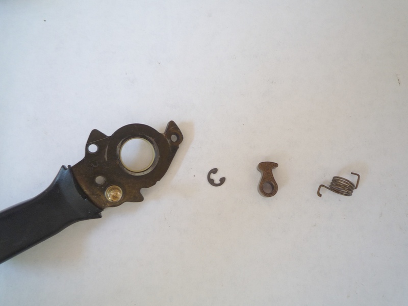 fig 17 |
Shimano Deore LX RapidFire Plus 3x8 Front Shifter
These are the parts of the front shifter in rough order of disassembly, going from the top down and left to right.
 fig 1 |
||
Front Shifter
- First, shift the shifter to the "L" setting, releasing tension
on the internal spring.
- Remove the one screw holding the bottom of the plastic
case on the shifter (fig 2).
- Note the position of the metal ring holding one spring end in
place (fig 3); the other spring end is on the lever.
- Unscrew large phillips screw, release tension on spring (fig 3).
(For reassembly:
hook lower spring end on lever, then upper spring end on metal ring; wind metal
ring ~90* CW (to put CCW tension on spring) until position matches
picture and metal ring drops down
onto grooves in post. Replace screw - note that this screw has
thread-lock on it from
the factory; you may want to put a mild thread-lock on the screw before
replacing.)
- Remove bushing and lever(fig 4). The lever has a spring-loaded
pawl on the underside, this will be disassembled later.
- For reassembly: note position of pawl mechanism inside shifter
(fig 5).
- Remove spring, bushing (this one is shallower than the previous
bushing), copper washer, and dust ring (fig 6).
For reassembly: the flat face of dust ring goes under lever.
- The shift lever is trapped underneath the plastic shifter housing.
Remove 2 screws on underside of indicator housing (fig 7) and
1 screw on topside of indicator housing (fig 8).
- Remove shift lever and housing (fig 9).
 fig 2 |
 fig 3 |
|
 fig 4 |
 fig 5 |
|
 fig 6 |
 fig 7 |
|
 fig 8 |
 fig 9 |
Front Shifter (cont.)
- Remove circlip that holds plate onto body; remove plate (and thin
washer underneath) (fig 10).
For reassembly: note that pawl underneath plate is under CCW tension,
and that shoulder of pawl is resting against tab.
- Note where spring end comes through pawl plate, and that the spring
force is pushing the pawl CCW against the toothed plate (fig 11).
- Remove the pawl plate, releasing the spring tension.
- Remove spring, plastic bushing, and toothed plate (fig 12).
For reassembly: note that spring end is in left-most hole; pawl plate
will need to be twisted ~90* CW to produce CCW tension on plate.
- Remove 2 screws holding bottom of indicator housing (fig 13).
- Cable holder is tensioned CW against metal block. Note the position
of the spring end. Remove indicator or hold it out of the way,
and lift cable holder up on post and release spring tension.
(fig 14).
- For reassembly: note which hole on the underside of the cable holder
is used for the other end of the spring. The cable holder is placed on the
post, then the spring end is inserted into the hole on the underside
of the cable holder, then the
cable holder is rotated CCW until it is past the block (alternatively
the other spring end can be pulled CW into its holder on the shifter housing)
.(fig 15).
- Remove spring and sleeve on housing post (fig 15).
- Disassemble shift lever/pawl assembly (fig 16,17).
- Clean each part, but DO NOT use any solvent that will degrade
the plastic
parts inside. No solvent may be necessary anyway, just a good wiping.
Relubricate everything that moves, and all contact/sliding surfaces
with a plastic-safe plastic/metal grease, and reassemble in the reverse
order. Remember to
read the notes in italic for reassembly.
 fig 10 |
 fig 11 |
|
 fig 12 |
 fig 13 |
|
 fig 14 |
 fig 15 |
|
 fig 16 |
 fig 17 |